
Datasheet for the ADM811/ADM812 voltage‑monitoring circuit with reset and manual‑reset features.
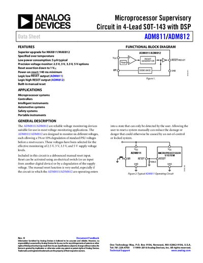
The ADM811/ADM812 are low‑power voltage supervisory devices that monitor 2.5 V, 3 V, 3.3 V and 5 V supplies. They provide a reset output that stays active for a typical 240 ms after power‑up and include a debounced manual‑reset input.
The device is offered in multiple suffix versions (L, M, T, S, R, Z) with different reset‑threshold voltages and is supplied in a 4‑lead SOT‑143 package. Electrical specifications, pin functions and ordering information are detailed in the following sections.
| Supply Voltage Range | 1.0 V – 5.5 V |
|---|---|
| Typical Supply Current | 8 µA (min) – 15 µA (typ) |
| Reset Voltage Threshold (ADM811L/ADM812L) | Typical 4.63 V |
| Reset Threshold Temperature Coefficient | 30 ppm/°C |
| VCC‑to‑RESET Delay | 40 µs |
| Reset Active Timeout Period | Typical 140 ms |
| Manual Reset Minimum Pulse Width | 10 µs |
| Glitch Immunity | 100 ns |
The devices operate from 1.0 V up to 5.5 V.
The internal timer holds the reset output active for a typical 240 ms after power‑up.
Typical supply current is 8 µA (minimum) to 15 µA (typical).
The circuit rejects glitches shorter than 100 ns.