
This application note provides information on using a gate resistor (RG) to control the switching of IGBTs. The information provided is only intended as guidance and does not provide complete design rules. The information is not exhaustive and the suitability of a design is for the user to decide.
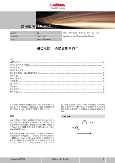
The guide provides design principles for using gate resistors (RG) to control IGBT switching. It covers the impact of RG on switching time, loss, dv/dt, di/dt, EMI and voltage spikes, and offers calculation methods for optimal resistor values.
Key sections include IGBT switching characteristics, free‑wheeling diode behavior, driver output stage, gate‑resistor calculation, minimum gate impedance, power dissipation, peak‑power capability, resistor types, layout recommendations, troubleshooting, and a glossary of symbols and terms. This manual is written in Chinese.
| RG(off) relationship | ≈ 2 × RG(on) |
|---|---|
| RG(on) vs RG(off) size | RG(on) is smaller than RG(off) |
The gate resistor influences the IGBT’s switching time and switching loss; a larger resistor slows the transition while a smaller resistor speeds it up.
RG(off) should be about twice the value of RG(on).
The minimum gate impedance is calculated using the formula shown in the guide under “最小栅极 阻抗的计算”.