
This document is the instruction manual for the DC1969A-A/DC1969A-B circuit board, which introduces the characteristics, functions and use methods of the circuit board
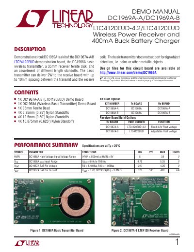
This manual provides step-by-step instructions for assembling and operating the DC1969A-A/DC1969A-B demonstration circuit board kit, which includes a wireless power transmitter and receiver. It details component specifications, build options, and operational procedures for testing the wireless power transfer system. The kit is designed for educational or prototyping use with the LTC4120EUD wireless power receiver and a basic transmitter.
The manual includes diagrams for proper equipment setup, measurement techniques, and theory of operation for the resonant power transfer system. It explains how to configure and test the transmitter and receiver boards, including alignment procedures and power measurements. It also covers the dynamic harmonization control (DHC) feature and how to adjust for different power transfer conditions.
| High Voltage Input Voltage Range | 8V to 38V |
|---|---|
| VCC Input Range | 4.75V to 5.25V |
| BAT Pin Voltage | 2.5V to 4.25V |
| BAT Pin Current | 370mA to 400mA |
The DC1968A basic transmitter is set to 130kHz operation.
When VIN is above 14V, DHC is inactive; when VIN falls below 14V, DHC grounds the pin to tune the receiver circuit to 127.4kHz.