
This is a battery management chip that can balance up to 12 lithium-ion batteries.
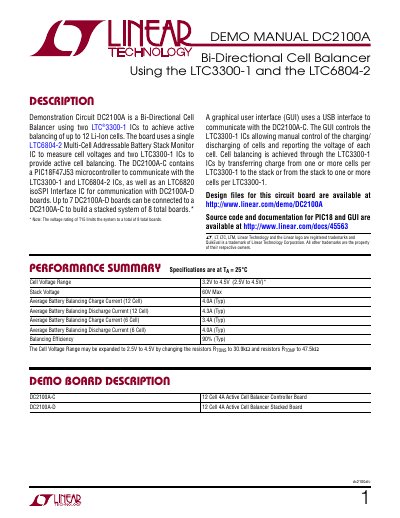
The DC2100A is a bi-directional cell balancer demonstration circuit designed to achieve active balancing of up to 12 Li-Ion cells. It utilizes two LTC3300-1 ICs for balancing and a single LTC6804-2 Multi-Cell Addressable Battery Stack Monitor IC to measure cell voltages. The DC2100A-C board includes a PIC18F47J53 microcontroller for communication with the ICs and an LTC6820 isoSPI Interface IC for connecting up to seven DC2100A-D stacked boards.
The system operates via a graphical user interface (GUI) that communicates with the board through a USB interface. This GUI allows for manual control of cell charging and discharging, reporting of individual cell voltages, and monitoring of system efficiency. The manual provides instructions for installing the QuikEval software, connecting the hardware, configuring the board ID jumpers, and using the GUI to manage the balancing process.
| Cell Voltage Range | 3.2V to 4.5V (2.5V to 4.5V) |
|---|---|
| Stack Voltage Max | 60V |
| Average Battery Balancing Charge Current (12 Cell) | 4.0A (Typ) |
| Average Battery Balancing Discharge Current (12 Cell) | 4.3A (Typ) |
| Balancing Efficiency | 90% (Typ) |
Up to 7 DC2100A-D boards can be connected to a DC2100A-C to build a stacked system of 8 total boards.
The QuikEval software must be installed on the PC to communicate with the board via USB.
The 4 bit board ID code is set by the A0 through A3 jumpers on the DC2100A-C, which must be set to 0000.