
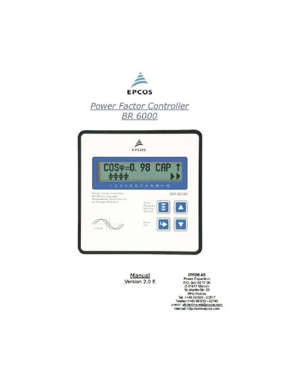
This manual covers the general description, installation, wiring, and safety requirements for the BR 6000 power factor controller. It explains current measurement, switching output options, alarm and fault handling, and the various operating modes such as automatic, manual, service, and expert mode.
Detailed sections describe programming of control series, the MODBUS interface, technical data, maintenance, warranty information, and troubleshooting. Annexes provide default settings, controller coupling details, and communication protocol specifications.
| Operating voltage | 230 VAC (L‑N) ±10% |
|---|---|
| Measuring voltage range | 30‑300 VAC (L‑N) |
| Measuring current | 5 A or 1 A (programmable) |
| Housing dimensions | 144 × 144 × 55 mm |
| Number of switching outputs | 6 or 12 (depending on version) |
| Display type | Illuminated graphic display, 2 × 16 characters |
| Quadrant operation | Four‑quadrant |
| Line parameters displayed | V, I, F, Q, P, S … |
| Harmonics display | Voltage and current harmonics |
| Temperature display | Yes |
| Capacitor power monitoring | Individual capacitor power values monitored |
| Maximum line‑parameter storage | Stored |
| No‑voltage turn‑off | Supported |
| Fault detection | Various statuses with interference‑message output |
| Communication baudrate | 9600 |
| Communication protocol | ODBUS |
The controller operates at 230 V ± 10% (230 VAC L‑N).
It provides either six or twelve switching outputs, depending on the version.
Generate an artificial fault by interrupting the measuring voltage; the alarm activates after about 10 minutes.