
This document describes how to boot on the ADSP-2192.
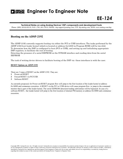
This document is an Engineer-to-Engineer Note (EE-124) from Analog Devices regarding the booting procedures of the ADSP-2192 digital signal processor. It details how the device boots via PCI or USB interfaces and explains the tasks performed by the loader kernel located in Program ROM at address 0x14000.
The note outlines three types of reset options: Power-on RESET, Forced RESET via PCI/USB, and Software RESET. It describes the flow where the loader kernel determines the boot mode, detects a serial EEPROM on the NVRAM interface if present, and configures appropriate DSP registers to facilitate the rest of the booting process.
| Architecture | 16-bit DSP with dual 219x cores |
|---|---|
| Loader Kernel Address | 0x14000 in Program ROM |
The ADSP-2192 currently supports booting via either the PCI or USB interfaces.
The three reset types are Power-on RESET, Forced RESET via PCI/USB, and Software RESET.
After a Power-on RESET, the program flow jumps to the first location of the loader kernel at address 0x14000.