
This application note will explain how to describe an ADSP-218x hardware memory architecture using the latest version of the ADSP-218x development tools, VisualDSP version 7.0
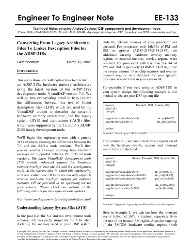
This document serves as a technical guide for developers transitioning from older Analog Devices development tools (versions 5.x and 6.x) to the VisualDSP 7.0 toolset. It details the differences between legacy system files and the new Linker Description Files (LDF) used to define hardware memory architecture for the ADSP-218x DSP family.
The guide provides specific examples of how to declare memory regions, such as Program Memory (PM) and Data Memory (DM), and how to handle hardware overlays. It covers the syntax for defining interrupt vector tables and mapping code modules to specific memory segments, offering a direct comparison between the old syntax and the new LDF format.
The document explains how to describe hardware memory architecture using VisualDSP version 7.0.
Program Memory segments must be declared as 24 bits using the WIDTH(24) LDF command.
Data Memory segments must be declared as 16 bits using the WIDTH(16) LDF command.