
This document is about synchronous buck MOSFET loss calculations, and provides an excel calculation model.
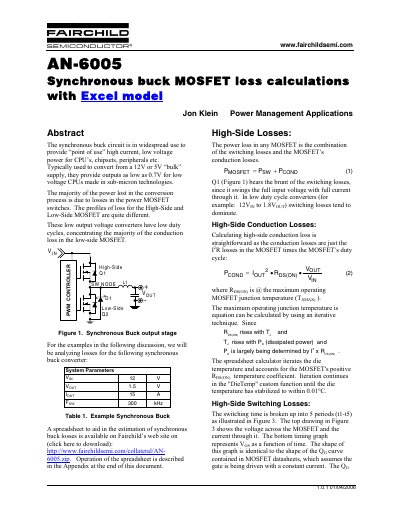
The document details the analysis of power loss in High-Side and Low-Side MOSFETs within a synchronous buck circuit. It focuses on scenarios where low output voltages result in low duty cycles, causing conduction loss to dominate in the low-side device while switching losses remain significant for the high-side device.
The text provides mathematical formulas for calculating various loss components, including gate charging power, output capacitance charging, and reverse recovery effects. It also describes an iterative technique used within a companion Excel spreadsheet to account for temperature-dependent resistance changes.
The majority of the power lost in the conversion process is due to losses in the power MOSFET switches.
In low duty cycle converters, the majority of the conduction loss concentrates in the low-side MOSFET.
The switching time is broken up into 5 periods (t1-t5) to analyze voltage and current profiles.