
Fairchild Semiconductor AN-9037 Assembly Guidelines for 8x8 MLP DriverMOS Packaging

This application note focuses on the soldering and back end processing of the 8x8 MLP
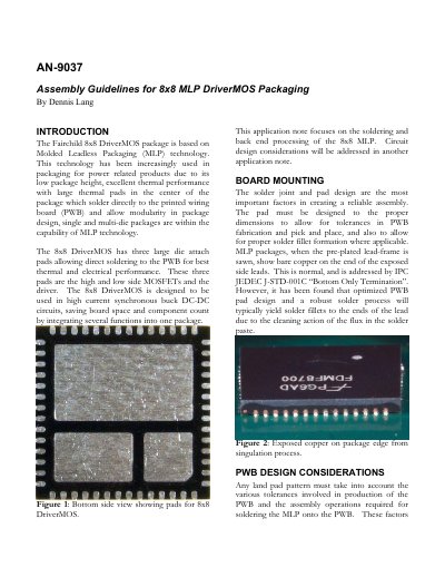

Fairchild Semiconductor AN-9037 Assembly Guidelines for 8x8 MLP DriverMOS Packaging - cover page
Brand
Fairchild
Category
Other Electronics
Document type
Application Note
Language
English
Pages
7
File format
PDF
File size
753 KB
Published
12 July, 2012
Updated
30 September, 2023
MD5 checksum
8F5838C09164B0E104A624F0BB40816F

About this manual

The document details the assembly process for the Fairchild 8x8 DriverMOS package, which utilizes Molded Leadless Packaging (MLP) technology. It covers critical factors such as PWB pad design, surface finishes like OSP and immersion nickel gold, and the use of vias within thermal pads to ensure reliable soldering.

What's inside

  • Introduction
  • Board Mounting
  • PWB Design Considerations
  • Pad Finish
  • Using Vias with 8x8 MLP
  • Stencil Design
  • Solder Paste
  • Reflow Profile
  • Voiding
  • Rework

Specifications

Package TypeMolded Leadless Packaging (MLP)
Peak Reflow Temperature260°C
Lead FinishNiPdAu
Recommended Solder AlloySAC 305 (96.5 Sn/3.0 Au/0.5 Cu)

Frequently asked questions

What is the maximum allowable voiding for this package?

Fairchild gives the customer the guideline of 25% voiding for MLP type components.

Can this component be reused after rework?

No, it is recommended that this component not be reused if rework becomes necessary.

What solder paste coverage percentage is recommended?

It was found that 52% coverage yielded good void performance while maintaining good standoff height.

Download PDF (753 KB)

More Fairchild Manuals


View all Fairchild manuals →