
Compool Cp3600 POOL-SPA CONTROL SYSTEM Installation & Operating Instructions
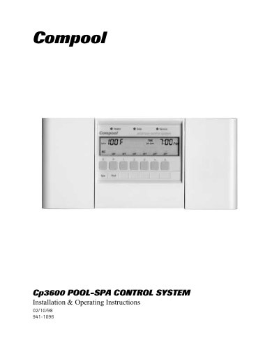
The Compool CP3600 Pool-Spa Control System is designed to manage pool and spa equipment. The package includes a control panel, power center, valve actuators, and sensor kits. Installation requires specific plumbing configurations for the 3-port valve and heater, as well as high and low voltage wiring connections to the power center.
| Control Panel | CP-3600 |
|---|---|
| Power Center | LX-3600 |
| Valve Actuator | CVA-24T |
| 3-Port Valve | PIV-2T |
| Sensor Kit | SNS-KIT2 |
The system includes a CP-3600 Control Panel, LX-3600 Power Center, two CVA-24T Valve Actuators, two PIV-2T 3-Port Valves, and one SNS-KIT2 Sensor Kit.
The 3-port valve should be plumbed on the suction-side of the filter pump with the center port connected to the pump, and on the output-side of the heater with the center port connected to the heater.
The terminal bar marked for equipment ground must be connected to the grounding means in the electrical supply panel with a continuous copper wire equivalent in size to the circuit conductors.