
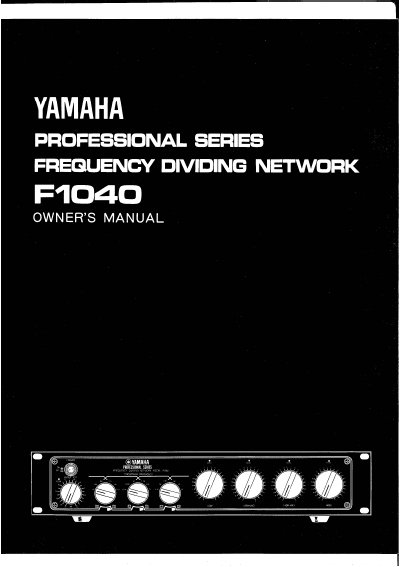
The Yamaha F1040 is a professional-grade four-way frequency dividing network designed for sound reinforcement and reproduction applications. It features four independent frequency ranges with individually selectable crossover frequencies, allowing for ultimate multi-amp system capability. The unit includes inputs and outputs with ground switches, balanced XLR connectors, and standard phone jacks, along with phase switches for each output.
| Number of frequency ranges | Four |
|---|---|
| Crossover frequencies | Six selectable per control |
| Rolloff slopes | 12 dB/oct or 18 dB/oct |
| Input attenuator range | 0 to -20 dB in 1 dB steps |
| High Pass Filter cutoff | 40 Hz |
| Output impedance (Low and Low-Mid) | 40 ohms |
| Output impedance (Mid-High and High) | 110 ohms |
| Voltage compatibility | 110-120 or 220-240AC, 50/60Hz |
The unit can operate in 4-way, 3-way-1, 3-way-2, or 2-way modes.
These switches couple or decouple the ground (shield) pin of the balanced input and output cannon connectors to eliminate inductive hum.