
This document is the datasheet of CDCR83 DIRECT RAMBUS CLOCK GENERATOR product released by Texas Instruments (TI). It describes the features and characteristics of the product in detail.
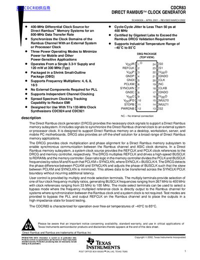
The CDCR83 Direct Rambus Clock Generator (DRCG) provides necessary clock signals to support Direct Rambus memory subsystems. It synchronizes the Direct Rambus channel clock with an external system or processor clock, supports frequency multipliers, and offers power-saving modes for mobile applications. The device operates from a single 3.3-V supply.
| Supply Voltage | 3.135 V to 3.465 V (Nominal 3.3 V) |
|---|---|
| Operating Temperature Range | -40 °C to 85°C |
| Typical Power Consumption at 300 MHz | 120 mW |
| Supported Frequency Multipliers | 4, 6, 8, 16/3 |
| Output Clock Range (BUSCLK) | 267 MHz to 400 MHz |
| Package Type | Shrink Small-Outline Package (DBQ) |
The device operates from a single 3.3-V supply and consumes 120 mW at 300 MHz (Typ).
No, it does not require any external components for the Phase Locked Loop.
The cycle-cycle jitter is less than 50 ps at 400 MHz.