
The ISL6524 is a power control and protection chip that integrates a PWM controller and three linear controllers. It provides power control and protection for four output voltages in high-performance microprocessor and computer applications. The chip integrates one PWM controller and three linear controllers, as well as monitoring and protection functions. The PWM controller regulates the microprocessor core voltage with a synchronous-rectified buck converter. One linear controller supplies power for the computer system's AGTL+ 1.2V bus. The other two linear controllers regulate power for the 1.5V AGP bus and the 1.8V power for the chip set core voltage and/or cache memory circuits. The ISL6524 includes an Intel VRM8.5 compatible, TTL 5-input digital-to-analog converter (DAC) that adjusts the microprocessor core-targeted PWM output voltage from 1.050V to 1.825V in 25mV steps. The precision reference and voltage-mode control provide ±1% static regulation. The linear regulators use external N-channel MOSFETs or bipolar NPN pass transistors to provide fixed output voltages of 1.2V ±3% (VOUT2), 1.5V ±3% (VOUT3), and 1.8V ±3% (VOUT4). The ISL6524 monitors all the output voltages and issues a delayed-rising VTT (VOUT2 output) Power Good signal before the core PWM starts to ramp up. Another system Power Good signal is issued when the core is within ±10% of the DAC setting and all other outputs are above their under-voltage levels. The chip also has built-in overvoltage protection.
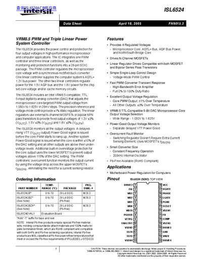
The ISL6524 is designed to provide power control and protection for four output voltages in high-performance microprocessor and computer applications. It integrates one PWM controller and three linear controllers into a 28-pin SOIC package. The PWM controller regulates the microprocessor core voltage using a synchronous-rectified buck converter, while the three linear regulators supply fixed output voltages of 1.2V, 1.5V, and 1.8V for AGTL+, AGP bus, and chipset/core memory circuits respectively.
| Ambient Temperature Range | 0°C to 70°C |
|---|---|
| Oscillator Frequency (Typical) | 200 kHz |
| DAC Output Voltage Range | 1.050V to 1.825V |
| Linear Regulator Tolerance | +3% over temperature |
The microprocessor core-targeted PWM output voltage adjusts from 1.050V to 1.825V in 25mV steps.
The device operates with a constant frequency using a 200kHz internal oscillator.
The linear regulators provide fixed output voltages of 1.2V, 1.5V, and 1.8V.