
The SY100S838/L is a low skew (÷1, ÷2/3) or (÷2, ÷4/6) clock generation chip designed explicitly for low skew clock generation applications. The internal dividers are synchronous to each other, therefore, the common output edges are all precisely aligned. The devices can be driven by either a differential or single-ended ECL or, if positive power supplies are used, PECL input signal. In addition, by using the VBB output, a sinusoidal source can be AC- coupled into the device. If a single-ended input is to be used, the VBB output should be connected to the CLK input and bypassed to ground via a 0.01µF capacitor. The VBB output is designed to act as the switching reference for the input of the SY100S838/L under single- ended input conditions. As a result, this pin can only source/sink up to 0.5mA of current. The Function Select (FSEL) input is used to determine what clock generation chip function is. When FSEL input is LOW, SY100S838/L functions as a divide by 2 and by 4/6 clock generation chip. However, if FSEL input is HIGH, it functions as a divide by 1 and by 2/3 clock chip. The common enable (EN) is synchronous so that the internal dividers will only be enabled/disabled when the internal clock is already in the LOW state. This avoids any chance of generating a runt clock pulse on the internal clock when the device is enabled/disabled as can happen with an asynchronous control. An internal runt pulse could lead to losing synchronization between the internal divider stages.
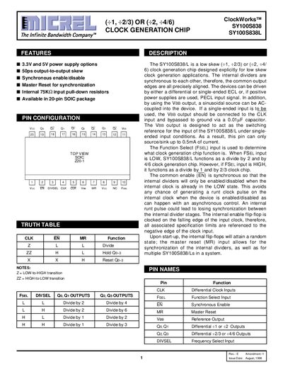
The Micrel SY100S838 and SY100S838L are low skew clock generation chips designed for ECL or PECL input signals. They offer synchronous enable/disable and a master reset function to synchronize internal dividers, ensuring precise alignment of common output edges. The devices are available in 20-pin SOIC packages with options for 3.3V and 5V power supplies.
| Power Supply Voltage | 3.3V and 5V options |
|---|---|
| Output-to-Output Skew | 50ps |
| Maximum Toggle Frequency | 1000 MHz |
| Package Type | 20-pin SOIC |
| Input Pull-down Resistors | 75KQ |
When FSEL is LOW, it functions as a divide by 2 and by 4/6 chip; if HIGH, it functions as a divide by 1 and by 2/3 chip.
It allows for the synchronization of the internal dividers, as well as for multiple devices in a system.