
VS6552 is a VGA resolution SmOP sensor module, featuring small physical size, ultra low power standby mode, integrated lens, class leading low light performance, high frame rate, low EMI link, etc.
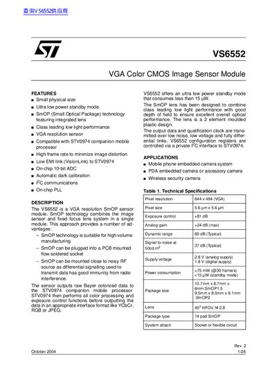
The STMicroelectronics VS6552 is a VGA resolution Small Optical Package (SmOP) sensor module that combines an image sensor and a fixed focus lens system in a single unit. It utilizes SmOP technology to offer advantages such as suitability for high-volume manufacturing, the ability to be plugged into a PCB-mounted flow soldered socket, and immunity from radio interference due to differential signaling.
The VS6552 outputs raw Bayer colorized data to the STV0974 companion mobile processor. The sensor features an ultra-low power standby mode consuming less than 15 mW and includes class-leading low light performance with a 45° horizontal field of view (HFOV) lens.
| Pixel resolution | 644 x 484 (VGA) |
|---|---|
| Pixel size | 5.6 um x 5.6 um |
| Dynamic range | 60 dB (Typical) |
| Supply voltage analog | 2.8 V |
| Supply voltage digital | 1.8 V |
| Power consumption standby | < 15 mW |
| Lens HFOV | 45° |
The ultra low power standby mode consumes less than 15 mW.
The sensor produces raw VGA digital video data at up to 30 frames per second.
The input clock pad accepts signals with frequencies up to 26 MHz.