
This document is the technical manual of U211B2/B3, which mainly introduces the function characteristics of the chip, including frequency-to-voltage converter, externally controlled integrated amplifier, overload limitation, soft start function, etc.
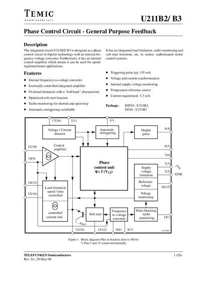
The U211B2/B3 semiconductor integrates a phase‑control circuit, an internal frequency‑to‑voltage converter and a control amplifier for speed‑regulated motor applications. It provides load‑limitation, tacho monitoring, soft‑start, automatic retriggering and pulse‑blocking features, all in a DIP18 or SO16 package.
The datasheet details the internal circuitry, design hints, absolute maximum ratings and recommended component values for applications such as motor speed control, mains‑direct supply, and overload protection. It also includes a policy statement on ozone‑depleting substances for the manufacturer.
| Pin 3 current requirement (‑Is) | 30 mA |
|---|---|
| Pin 1 synchronization current (Isynet) | 5 mA |
| Pin 8 input current (f/V converter) | 3 mA |
| Pin 12 input current | 500 pA |
| Maximum reverse voltage (Pin 4) | 5 V |
The datasheet specifies a maximum current requirement of 30 mA for Pin 3.
When the supply voltage rises, the integrated soft‑start circuit begins charging a capacitor; the voltage across this capacitor follows the phase‑control input, providing a gentle motor start and limiting inrush current.
Pin 12 may be driven between 0 V and 7 V relative to the reference point on Pin 2.