
This datasheet lists in detail the maximum ratings, thermal characteristics, device marking and resistor values of DTC114E/D digital transistors.
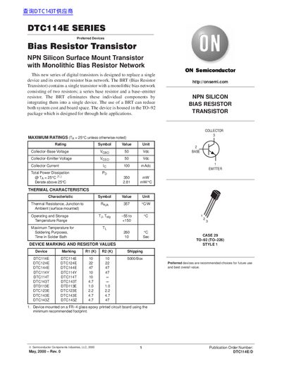
The DTC114E series are NPN silicon surface‑mount transistors that integrate a monolithic bias resistor network, reducing component count and board space. They are supplied in a TO‑92 package for through‑hole mounting and are intended for level‑shifting, open‑collector inverters, and inexpensive current‑source applications.
The datasheet provides maximum ratings, detailed electrical characteristics, typical performance curves, and recommended application circuits. It also includes ordering information and legal notices from ON Semiconductor.
| Collector‑Base Voltage (VcBO) | 50 V |
|---|---|
| Collector‑Emitter Voltage (VcEO) | 50 V |
| Collector Current (Ic) | 100 mA |
| Thermal Resistance (J‑A) | 357 °C/W |
| Operating Temperature Range | -55 °C to +150 °C |
| Maximum Soldering Temperature | 260 °C |
| Input Resistor (Ri) – Typical | 7.0 kΩ |
The devices are housed in a TO‑92 package for through‑hole applications.
The maximum collector‑emitter voltage is 50 V.
The typical input resistor (Ri) for DTC114E is 7.0 kΩ.