
EMG4 / UMG4N / FMG4A is a NPN 100mA 50V complex digital transistor produced by ROHM, which has built-in bias resistors and completely isolated thin film resistors. It can be used in switch circuits, interface circuits and driver circuits.
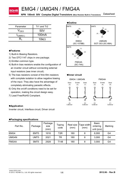
The EMG4, UMG4N and FMG4A are NPN 100 mA 50 V complex digital transistors with built‑in bias resistors, offered in SOT‑353 (SC‑88A) and SC‑74A packages. They feature an emitter‑common configuration and integrated thin‑film bias resistors that enable inverter circuits without external input resistors.
These RoHS‑compliant devices are intended for inverter, interface and driver circuits in audio‑visual, office‑automation, communication and consumer electronic equipment. The datasheet provides absolute maximum ratings, electrical characteristics, characteristic curves and mechanical dimensions.
| Collector‑emitter voltage (Vceo) | 50 V |
|---|---|
| Collector current (Ic max) | 100 mA |
| Power dissipation (EMG4/UMG4N) | 150 mW |
| Power dissipation (FMG4A) | 300 mW |
| Junction temperature (Tj) | 150 °C |
| Storage temperature range | -55 °C to +150 °C |
| Input resistance | 10 kΩ (typ) |
The maximum collector‑emitter voltage is 50 V.
Built‑in biasing resistors allow an inverter circuit to be configured without external input resistors.
Typical applications include inverter circuits, interface circuits, and driver circuits.