
The document describes the features and characteristics of EMG1 / UMG1N / FMG1A NPN 100mA 50V Complex Digital Transistors (Bias Resistor Built-in Transistors).
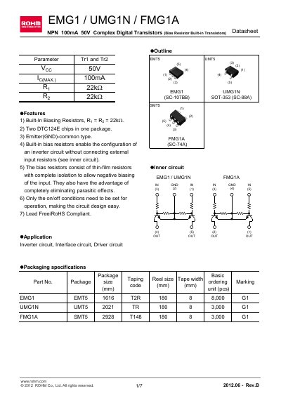
The EMG1, UMG1N and FMG1A are NPN 100 mA 50 V complex digital transistors with built‑in bias resistors (Ry = Re = 22 kΩ). Each package contains two DTC124E chips, uses an emitter‑common configuration, and eliminates the need for external input resistors. The devices are lead‑free, RoHS‑compliant, and intended for inverter, interface, and driver circuits.
Key specifications include a 50 V supply rating, -10 V to +40 V input range, up to 100 mA collector current, and power dissipation of 150 mW (EMG1) or 300 mW (UMG1N/FMG1A). Package types are EMT5 (SOT‑353), UMT5 (SOT‑353) and SMT5 (SOT‑353) with dimensions ranging from 1.6 mm to 2.9 mm. The datasheet also lists absolute maximum ratings, electrical characteristic curves, and typical application examples.
| Supply voltage (Voc) | 50 V |
|---|---|
| Input voltage range | -10 to +40 V |
| Output current (Io) | 30 mA |
| Collector current max (Ic) | 100 mA |
| Power dissipation (EMG1) | 150 mW |
| Power dissipation (UMG1N/FMG1A) | 300 mW |
| Junction temperature (Tj) | 150 °C |
| Storage temperature range | -55 to +150 °C |
| Built‑in bias resistor value | 22 kΩ |
| Package size (EMG1) | 1.6 mm × 1.6 mm (EMT5) |
The maximum supply voltage is 50 V.
Both bias resistors are 22 kΩ.
They are used in inverter circuits, interface circuits, and driver circuits.