
NJG1553BF is a GaAs MMIC MIXER IC from NJG, with built-in local amplifier for 1.9GHz PCS applications. This mixer features high conversion gain, low noise figure and low distortion.
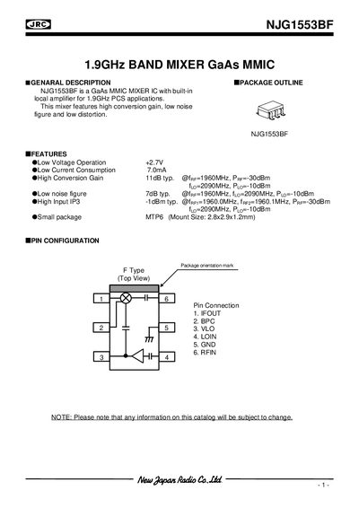
The NJG1553BF is a GaAs MMIC mixer IC designed for 1.9 GHz PCS use. It integrates a local amplifier and provides features such as low voltage operation (+2.7 V), low current consumption (7 mA), high conversion gain (11 dB typ.), low noise figure (7 dB typ.) and a high input IP3 (-1 dBm typ.).
Electrical specifications include a recommended supply voltage of 2.5‑2.7‑5.8 V, mixer current up to 7 mA, conversion gain of 9‑11 dB, and noise figure of 7‑8.5 dB. The document also gives typical PCB design guidelines (FR‑4, 0.5 mm thickness, 1 mm microstrip width, 22.5 × 30.0 mm board) and handling precautions for the GaAs device.
| Supply Voltage (Mixer) | 2.5 V min / 2.7 V typ / 5.8 V max |
|---|---|
| Supply Voltage (Local Amplifier) | 2.5 V min / 2.7 V typ / 5.8 V max |
| Mixer Current | 5.0 mA min / 7.0 mA max |
| Local Amplifier Current | 2.0 mA min / 3.2 mA max |
| Conversion Gain | 9 dB min / 11 dB max |
| Noise Figure | 7.0 dB min / 8.5 dB max |
| Input Third‑Order Intercept Point (IIP3) | -1 dBm typ |
| Operating RF Frequency | 1930 MHz min / 1990 MHz max |
| Package Type | MTP6, 2.8 × 2.9 × 1.2 mm |
The recommended supply voltage range is 2.5 V minimum, 2.7 V typical, and up to 5.8 V maximum.
It uses an MTP6 surface‑mount package measuring 2.8 × 2.9 × 1.2 mm.
Use an FR‑4 board 0.5 mm thick, microstrip line width of 1 mm, and a board size of 22.5 × 30.0 mm.
The typical conversion gain is 11 dB, with a range from 9 dB to 11 dB.