
This document describes the AC loop of RSLIC18, including architectural description and voltage feed current sense.
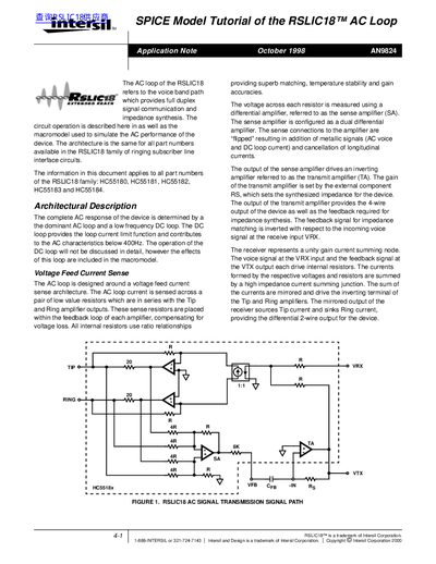
The note describes the functional blocks of the RSLIC18 AC loop, including the receiver, tip and ring amplifiers, sense amplifier, and transmit amplifier. It explains how the sense amplifier measures resistor voltages, how the transmit amplifier uses an external resistor RS to synthesize impedance, and how the overall loop provides a 4‑wire output.
A SPICE macromodel of the entire AC loop is presented, with separate pole models for each amplifier. Simulation examples for resistive and complex loads show expected magnitude and phase responses, and a complete SPICE net list is provided for use in any SPICE‑compatible simulator.
| Tip amplifier open‑loop gain | 49740 (94 dB) |
|---|---|
| Tip amplifier 3‑dB bandwidth | 13 Hz |
| Ring amplifier open‑loop gain | 59420 (95 dB) |
| Ring amplifier 3‑dB bandwidth | 12 Hz |
| Sense amplifier open‑loop gain | 4716 (73 dB) |
| Sense amplifier 3‑dB bandwidth | 260 Hz |
| Transmit amplifier open‑loop gain | 4151 (72 dB) |
| Transmit amplifier 3‑dB bandwidth | 127 Hz |
| External resistor RS programming equation | RS = 400 × Zp |
The document applies to all part numbers of the RSLIC18 family: HC55180, HC55181, HC55182, HC55183 and HC55184.
RS is calculated as 400 times the target impedance Zp; for example, with Zp = 530 Ω the resistor value is 212 kΩ.
The Tip amplifier has an open‑loop gain of 49 740 (94 dB).
Both resistive‑load and complex‑load simulations are shown, with magnitude and phase plots from 10 Hz to 10 kHz and numerical tables of results.