
This document is the user manual for Delta Temperature Controller DTB Series and B Series. It includes precautions and safety warnings before use, recommended wiring methods, and installation environments. The temperature controller is protected by double insulation or reinforced insulation, equivalent to Class II of IEC 536. It is suitable for wire sizes from 2 mm2 to 24AWG. Users are advised to comply with safety regulations, ensure proper wiring and installation, and avoid electric shock and equipment malfunction.
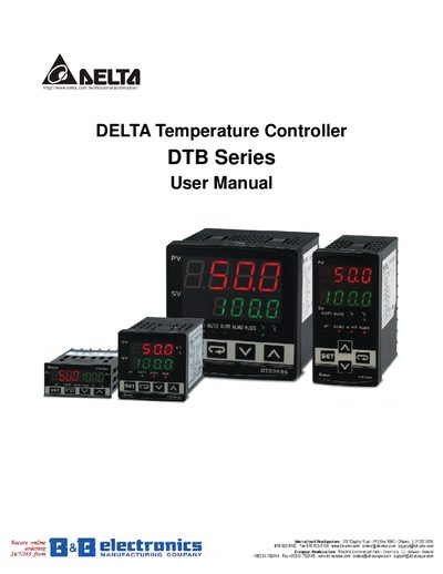
The DTB Series Temperature Controllers from Delta are open‑type devices designed for precise temperature regulation in industrial applications. They support a wide range of sensor types, including thermocouples and platinum RTDs, and offer multiple output options such as relay, voltage pulse, current, and linear voltage.
This manual covers safety warnings, wiring guidelines, display functions, operation modes (PID, ON/OFF, manual, program control), dual‑loop heating/cooling control, alarm output configuration, communication settings (MODBUS ASCII/RTU), and full technical specifications. It also includes ordering information for the various DIN‑size models.
| Input Voltage | 100 to 240VAC 50/60Hz |
|---|---|
| Operation Voltage Range | 85% to 110% of rated voltage |
| Power Consumption | SVA max. |
| Memory Protection | EEPROM 4k bit (non‑volatile, 100,000 writes) |
| Display Method | 2 line x 4 character 7‑segment LED |
| RTD Sensor Types | 3‑wire Pt100, JPt100 |
| Analog Input Range | 0‑5V, 0‑10V, 0‑20 mA, 4‑20 mA, 0‑50 mV |
| Control Mode | PID, ON/OFF, Manual, PID program (Ramp/Soak) |
| Relay Output | SPDT (SPST for 1/16 DIN & 1/32 DIN), 250 VAC, 5 A |
| Voltage Pulse Output | DC 14 V, max 40 mA |
| Current Output | DC 4 ~ 20 mA (max load 600 Ω) |
| Linear Voltage Output | 0 ~ 5 V, 0 ~ 10 V |
| RS‑485 Communication | MODBUS ASCII / RTU |
| Vibration Resistance | 10‑55 Hz, 10 m/s² for 10 min (X, Y, Z) |
| Shock Resistance | Max 300 m/s², 3 times each axis |
| Ambient Temperature Range | 0 °C to +50 °C |
| Storage Temperature Range | -20 °C to +65 °C |
| Maximum Altitude | 2000 m or less |
| Relative Humidity | 35 % to 80 % (non‑condensing) |
Do not touch the AC terminals while power is applied, disconnect power before opening the unit, avoid dust, moisture, corrosive gases, and never modify or disassemble the controller.
The controller communicates via RS‑485 using the MODBUS ASCII or RTU protocol.
Up to three alarm output groups are provided, each supporting thirteen alarm types such as deviation limits, absolute limits, and CT alarms.
The controller can operate in PID, ON/OFF, Manual, or PID program (Ramp/Soak) modes.