
This application note describes how to drive RGB LEDs, how to calculate a power dissipation, how to design an over temperature protection, how to use a software PWM modulation and why over voltage protection should be implemented for this kind of application.
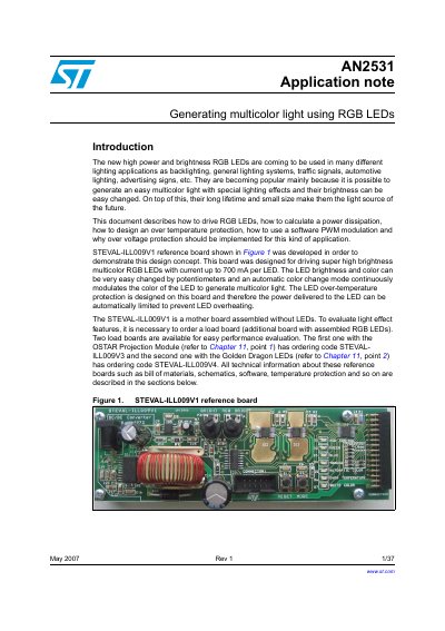
The document describes the design and operation of a high‑power RGB LED driver system based on the STEVAL‑ILL009V1 reference board. It explains the driving concept, power‑dissipation calculations, over‑temperature and over‑voltage protection, and software PWM modulation for color control.
Two load boards (STEVAL‑ILL009V3 with an OSTAR projection module and STEVAL‑ILL009V4 with Golden Dragon LEDs) are provided for evaluation. Detailed schematics, bill of materials, and design calculations are included for both the reference board and the load boards.
| Constant current range per channel | 80‑500 mA |
|---|---|
| Maximum board current capability | 700 mA total (2 × 350 mA) |
| LED driver part number | STP04CM596 |
| Temperature sensor part number | STLM20 |