
This application note describes an intelligent multipower digital ballast for fluorescent lamps. It explains the features and characteristics of the product, such as better efficiency, increased lamp life, lightweight design, etc.
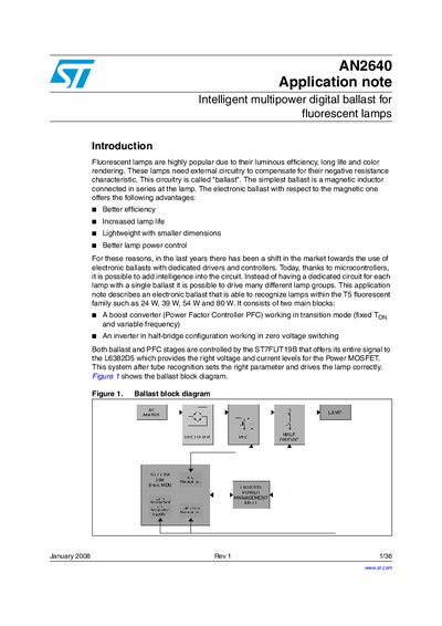
This application note (AN2640) presents an intelligent multipower digital ballast that can drive T5 fluorescent lamps of 24 W, 39 W, 54 W and 80 W. The design uses a boost converter (PFC) and a half‑bridge inverter, both controlled by an ST7FLIT19B MCU and a L6382D5 power‑management IC.
The document details the PFC section design, boost inductor selection, half‑bridge criteria, component choices, recognition technique, board schematic, bill of materials and experimental results such as efficiency, THD and electromagnetic compatibility.
| Input capacitor | 470 nF |
|---|---|
| Output bulk capacitor | 47 µF |
| Output voltage | 420 V |
| Boost inductor value | 2 mH (±5%) |
| Half‑bridge resonant inductor | 1.2 mH |
| Startup capacitor | 10 nF |
| Minimum switching frequency | 35 kHz |
The regulated DC output voltage is 420 V.
The ST7FLIT19B 8‑bit microcontroller controls both stages.
A 470 nF input capacitor is used.