
SN54AHC574, SN74AHC574 are octal edge-triggered D-type flip-flops with 3-state outputs designed specifically for driving highly capacitive or relatively low-impedance loads. These devices are particularly suitable for implementing buffer registers, I/O ports, bidirectional bus drivers, and working registers. On the positive transition of the clock (CLK) input, the Q outputs are set to the logic levels of the data (D) inputs. A buffered output-enable (OE) input places the eight outputs in either a normal logic state (high or low) or the high-impedance state. In the high-impedance state, the outputs neither load nor drive the bus lines significantly. The high-impedance state output current consumption is very low, typically less than 100µA.
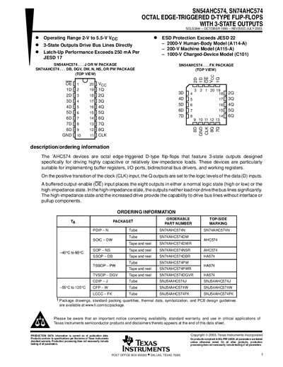
The SN54AHC574 and SN74AHC574 devices are octal edge‑triggered D‑type flip‑flops featuring 3‑state outputs. They are intended for buffer registers, I/O ports, bidirectional bus drivers, and working registers, allowing the outputs to be placed in a normal logic state or a high‑impedance state.
The datasheet provides electrical characteristics, timing requirements, package options, and ordering information. It includes absolute maximum ratings, recommended operating conditions, switching and noise characteristics, as well as mechanical data for the various package types.
| Supply voltage range | 2 V to 5.5 V |
|---|
OE should be tied to VCC through a pull‑up resistor; the resistor value must be large enough for the driver’s current‑sinking capability.