
Description of HCC4054B/55B/56B HCF4054B/55B/56B Liquid-Crystal Display Drivers. Quiescent current specified to 20V for HCC device. Operation of liquid crystals with COS/MOS circuits provides ultra-low-power displays. Equivalent AC output drive for liquid-crystal displays-no external capacitor required. Voltage doubling across display [(VDD – VEE) = 18V)] results in effective 36V (p-p) drive across selected display segments. Low- or high-output level DC drive for other types of displays. On-chip logic-level conversion for different input and output-level swings. Full decoding of all input combinations: “0-9, L, H, P, A–” and blank positions. Input current of 100nA at 18V and 25°C for HCC device. 100% tested for quiescent current. Meets all requirements of JEDECTEN tative standard N°. 13A, “Standard Specifications for Description of “B” Series CMOS Devices”.
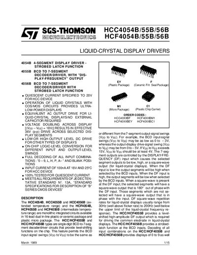
The SGS‑THOMSON HCC/HCF4054B, 4055B and 4056B are monolithic integrated circuits designed for driving liquid‑crystal displays and BCD‑to‑7‑segment decoding. The family provides level‑shifting, strobe‑latch functions and a high‑amplitude display‑frequency output suitable for LCD segment driving.
The document includes absolute maximum ratings, recommended operating conditions, static and dynamic electrical characteristics, functional diagrams, pin connections, typical applications and mechanical dimensions. It is intended for designers and engineers who need detailed specifications for circuit implementation.
| Supply Voltage (Vop) – HCC Types | -0.5 V to +20 V |
|---|---|
| Supply Voltage (Vop) – HCF Types | -0.5 V to +18 V |
| Input Voltage (Vi) Range | 0.5 V to Vop + 0.5 V |
| Total Power Dissipation (Ptot) | 200 mW per package |
| Operating Temperature – HCC Types | -55 °C to +125 °C |
| Operating Temperature – HCF Types | -40 °C to +85 °C |
| Input Current per Input (HCC) | 100 nA at 18 V, 25 °C |
The HCC devices can be powered from –0.5 V up to +20 V.
HCF devices are specified to operate between –40 °C and +85 °C.
Each input draws about 100 nA at 18 V and 25 °C for the HCC version.
The device dissipates up to 200 mW per package under the specified conditions.