
STK503 user guide introduces the basic features and usage methods of STK503, including STK503 hardware overview, installation, usage methods and troubleshooting
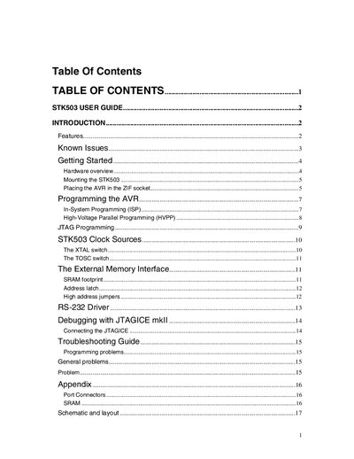
This guide introduces the STK503 top module for the STK500 development board, describing its hardware features such as the 100‑pin ZIF socket, on‑board RS‑232 converter, clock source switches, SRAM footprint, and port connectors for ports E‑L. It also covers mounting the module on the STK500 and installing AVR devices.
Four programming options are detailed: In‑System Programming (ISP), High‑Voltage Parallel Programming (HVPP), JTAG programming, and self‑programming (refer to the AVR datasheet). The guide provides step‑by‑step procedures, jumper settings, and software instructions for using AVR Studio to program supported AVR devices.
| Supported AVR devices | ATmega2560, ATmega1280, ATmega640 |
|---|---|
| ZIF socket type | 100‑pin TQFP |
| RS‑232 voltage range | 1.8 V to 5.5 V |
| On‑board crystal frequency | 32 kHz |
| Port connectors | Ports E, F, G, H, J, K, L |
| SRAM footprint | User‑mountable SRAM chip (various types) |
| Clock source switches | Two switches for on‑board and external clock sources |
The target voltage must be set to 5 V before performing High‑Voltage Parallel Programming.
The STK503 supports ATmega2560, ATmega1280, and ATmega640 devices.