
This document is an introduction to AT89C2051, which is a low-voltage, high-performance CMOS 8-bit microcontroller with 2KB of Flash programmable and erasable read only memory (PEROM).
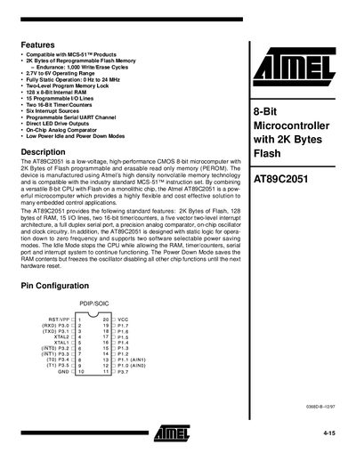
The AT89C2051 microcontroller combines a CMOS 8‑bit CPU with 2 KB of on‑chip Flash memory, 128 bytes of RAM and a range of peripherals such as two 16‑bit timer/counters, a serial UART, an analog comparator and direct LED drive outputs. It operates from 2.7 V to 6 V and can run at frequencies up to 24 MHz, with idle and power‑down modes for low‑power applications.
The document provides pin configurations, special function registers, programming procedures for the Flash memory, timing characteristics, and ordering information for commercial, industrial and automotive package variants.
| Internal RAM | 128 bytes (8‑bit) |
|---|---|
| Programmable I/O lines | 15 |
| Timer/Counters | Two 16‑bit |
| Operating voltage range | 2.7 V to 6 V |
| Maximum CPU frequency | 24 MHz |
| Power modes | Idle and Power‑Down |
| Analog comparator | On‑chip |
| LED drive capability | Direct drive outputs |
The device operates from 2.7 V to 6 V.
It provides 15 programmable I/O lines.
The microcontroller supports an Idle mode, where the CPU sleeps but peripherals stay active, and a Power‑Down mode, which stops the oscillator and retains RAM until reset.
Flash is programmed one byte at a time using a sequence of control signals on pins RST, P3.2‑P3.7 and XTAL1, with a typical write cycle of about 1.2 ms.