
MAX2232/MAX2233 are low-voltage, silicon RF power amplifiers (PAs) designed for use in the 900MHz ISM band. They operate from a single +2.7V to +5.5V supply, allowing them to be powered directly from a 3-cell NiCd or a 1-cell Lithium-Ion battery. The devices typically deliver 250mW (+24dBm) of output power at 915MHz from a single +3.6V supply, or 150mW (+22dBm) from a single +2.7V supply. At +24dBm out- put power, power-added efficiency (PAE) is 44%. The MAX2232/MAX2233 provide 24dB of gain, which is adjustable over a continuous 24dB span via the analog gain-control pin of the MAX2232 or in two 10dB steps via the 2-bit programmable gain-control DAC of the MAX2233. An external capacitor sets the RF output power envelope ramp time, reducing spurious emis- sions during power-up and power-down by providing a gradual change in output power (MAX2232). The MAX2232/MAX2233 feature a low-power shutdown mode, which typically draws less than 1µA of supply current, saving power during “idle slots” in time-division multiple-access (TDMA) systems. The ∆VSWR of the RF input in shutdown mode relative to normal operation is 1.2:1. The devices also feature a thermal shutdown function, enabling the PA to protect itself from excessive temperature conditions that could damage the IC. A capacitor to ground limits thermal cycling by setting a thermal shutdown timeout period. The MAX2232/MAX2233 are available in a space-sav- ing, thermally enhanced 16-pin power-QSOP (PQSOP) package.
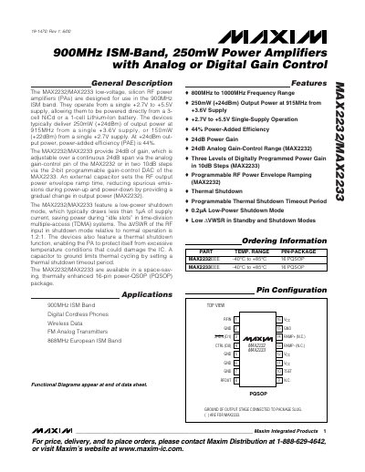
The MAX2232 and MAX2233 are low‑voltage silicon RF power amplifiers designed for the 900 MHz ISM band. They operate from a single +2.7 V to +5.5 V supply and can be powered directly from a 3‑cell NiCd or a 1‑cell Li‑Ion battery. Typical output is 250 mW (24 dBm) at 915 MHz from a +3.6 V supply, with a power‑added efficiency of 44 %.
Both devices provide 24 dB of gain. The MAX2232 offers continuous analog gain control, while the MAX2233 uses a 2‑bit digital gain‑control DAC for three 10 dB steps. Features include low‑power shutdown (<0.2 µA), programmable thermal shutdown, and a 16‑pin thermally enhanced PQSOP package.
| Frequency Range | 800 MHz – 1000 MHz |
|---|---|
| Output Power (typical) | 250 mW (24 dBm) at 915 MHz, +3.6 V supply |
| Supply Voltage | +2.7 V to +5.5 V |
| Gain | 24 dB (continuous analog or three 10 dB digital steps) |
| Shutdown Supply Current | < 0.2 µA |
| Standby Supply Current | ≈ 20 mA |
The devices operate from +2.7 V to +5.5 V single‑supply.
They can deliver up to 250 mW (24 dBm) at 915 MHz when powered from +3.6 V.
Gain is varied continuously over 24 dB by applying a voltage between 0.6 V and 2.2 V to the analog CTRL pin.