
ADP190/ADP191 are logic-controlled high-side power switches with features such as low RDSON, internal output discharge resistor, turn-on slew rate limiting, etc.
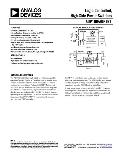
The ADP190/ADP191 are high‑side load switches designed for operation from 1.1 V to 3.6 V, providing up to 500 mA continuous current with low on‑resistance. They include features such as an internal level‑shifter, ultra‑low ground current (<2 pA), and an optional discharge resistor in the ADP191 version.
The document contains detailed specifications, timing diagrams, absolute maximum ratings, thermal data, pin configuration, typical performance curves, and ordering information for the ultra‑small 0.8 mm × 0.8 mm 4‑ball WLCSP package.
| Continuous operating current | 500 mA |
|---|---|
| Typical RDS(on) at 1.8 V | 105 mΩ |
| Package | 0.8 mm × 0.8 mm 4‑ball WLCSP |
The devices support up to 500 mA of continuous operating current.
Typical RDS(on) is 105 mΩ when powered at 1.8 V.
It is offered in an ultra‑small 0.8 mm × 0.8 mm 4‑ball WLCSP package.