
This is a maintenance manual for KD-LX333R
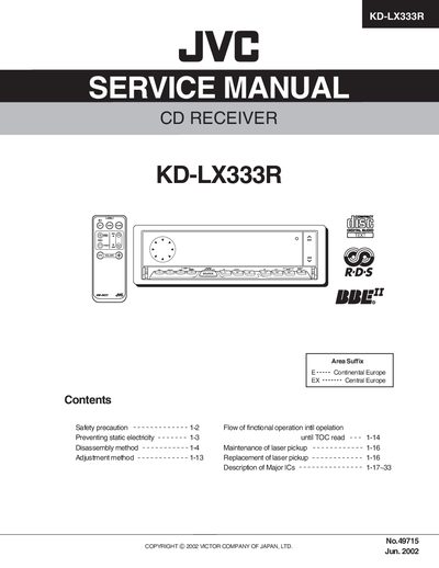
This service manual covers safety precautions, static‑electricity prevention, and step‑by‑step disassembly and adjustment methods for the JVC KD‑LX333R CD receiver. It also describes the flow of functional operation, maintenance and replacement of the laser pickup, and details the major integrated circuits used in the unit.
Technical sections include extensive pin‑function tables for the TC9490FA DSP/DAC and related components, power‑supply pin definitions, and complete electrical parts lists for both the main board and front board. The document is intended for service technicians performing repair, calibration, or component replacement.
| Digital power supply voltage (VDD3) | 3.3 V |
|---|---|
| Analog power supply voltage (AVDD3) | 3.3 V |
| Bit clock output selectable rates | 32 fs, 48 fs, or 64 fs |
Pin 1 (BCK) is the bit‑clock output, selectable for 32 fs, 48 fs, or 64 fs by command.
The digital power pins (VDD3) are supplied with 3.3 V.
The manual lists pins numbered up to 64, covering all I/O functions of the receiver.