
The NCP1027 is a high-voltage switcher designed for medium power offline switch mode power supplies (SMPS) with low standby power. It utilizes proprietary high-voltage technology that allows for the integration of a power MOSFET and startup current source directly connected to the bulk capacitor. An adjustable brown-out circuitry prevents lethal runaway in low input voltage conditions until a sufficient input level is reached. Current-mode operation and adjustable ramp compensation provide superior performance in universal mains applications. Additionally, an Over Power Protection pin enables precise compensation of internal delays in high input voltage conditions and optimization of the maximum output current capability. Protection features include a timer that detects overload or short-circuit conditions and stops all operations, ensuring safe auto-recovery with low duty cycle burst operation. An integrated auto-recovery Overvoltage Protection monitors the VCC level and temporarily shuts down driving pulses in case of unexpected feedback loop runaway. The circuit's excellent RDS(on) figure makes it an ideal choice for standby/auxiliary offline power supplies or applications requiring higher output power levels.
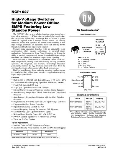
The NCP1027 is a high‑voltage switcher designed for medium‑power offline SMPS applications, offering a built‑in 700 V MOSFET and a range of protection features such as brown‑out, over‑power, and over‑voltage detection. It operates in current‑mode with selectable frequencies of 65 kHz or 100 kHz and includes an internal startup current source for clean power‑up.
Typical applications include medium‑power AC‑DC adapters for chargers and auxiliary/standby power supplies for ATX and TVS power supplies. The document details pin functions, maximum ratings, electrical characteristics, and ordering information for the PDIP‑8 package.
| Built‑in MOSFET voltage rating | 700 V |
|---|---|
| Typical MOSFET Rds(on) | 5.8 mΩ (Typ @ 25 °C) |
| Drain voltage rating (BVdss) | 700 V |
| Peak drain current during saturation | 18 A |
| No‑load standby power | 85 mW @ 265 Vac |
| Loaded input power | 715 mW @ 230 Vac |
| Output voltage/current (Vout) | 5.0 V / 3.0 A |
| Switching frequency | 65 kHz (typical) |
| Maximum duty cycle | 80 % (typical) |
It includes a built‑in 700 V MOSFET with a typical on‑resistance of about 5.8 mΩ at 25 °C.
The no‑load input standby power is 85 mW when operating at 265 Vac.
Typical applications are medium‑power AC‑DC adapters for chargers and auxiliary/standby power supplies for ATX and TVS power supplies.