
UC1852 provides a low-cost solution to active power-factor correction (PFC) for systems that would otherwise draw high peak current pulses from AC power lines. This circuit implements zero-current switched boost conversion, producing sinusoidal input currents with a minimum of external components, while keeping peak current substantially below that of fully-discontinuous converters. The UC1852 provides controlled switch on-time to regulate the output bulk DC voltage, an off-time defined by the boost inductor, and a zero-current sensing circuit to reactivate the switch cycle. Even though switching frequency varies with both load and instantaneous line voltage, it can be maintained within a reasonable range to minimize noise generation. The ability to obtain a power factor in excess of 0.99 makes the UC1852 an optimum choice for low-cost applications in the 50 to 5.
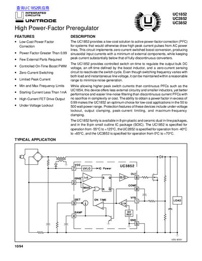
The UC1852 family provides low‑cost active power‑factor correction solutions with a power factor greater than 0.99 and minimal external components. These devices implement zero‑current switched boost conversion, offering high‑current FET drive output and under‑voltage lockout protection.
Three models are offered (UC1852, UC2852, UC3852) in 8‑pin DIP, ceramic DIP, and 8‑pin SOIC packages, covering operating temperature ranges from –55 °C to +125 °C (UC1852) down to 0 °C to +70 °C (UC3852). Typical applications include 100 W power‑factor preregulators operating from 90 V to 160 V RMS.
| Operating Temperature Range (UC1852) | -55 °C to +125 °C |
|---|---|
| Operating Temperature Range (UC2852) | -40 °C to +85 °C |
| Operating Temperature Range (UC3852) | 0 °C to +70 °C |
| Power Factor | > 0.99 |
| Input Voltage Range (application example) | 90 V to 160 V RMS (50 Hz‑60 Hz) |
| Package Types | 8‑pin DIP, 8‑pin ceramic DIP, 8‑pin SOIC |
The UC1852 operates from –55 °C to +125 °C.
It provides a power factor greater than 0.99.
The circuit works with an input of 90 V to 160 V RMS at 50 Hz to 60 Hz.
The family is offered in 8‑pin plastic DIP, ceramic DIP, and 8‑pin SOIC packages.