
The TL1454A/TL1454AY is a dual-channel pulse-width modulation (PWM) control circuit primarily intended for low-power dc/dc converters. Applications include LCD displays, backlight inverters, notebook computers, and other products requiring small, high-frequency, dc/dc converters. Each PWM channel has its own error amplifier, PWM comparator, dead-time control comparator, and MOSFET driver. The voltage reference, oscillator, undervoltage lockout, and short-circuit protection are common to both channels. Channel 1 is configured to drive n-channel MOSFETs in step-up or flyback converters, and channel 2 is configured to drive p-channel MOSFETs in step-down or inverting converters. The operating frequency is set with an external resistor and an external capacitor, and dead time is continuously adjustable from 0 to 100% duty cycle with a resistive divider network. Soft start can be implemented by adding a capacitor to the dead-time control (DTC) network. The error-amplifier common-mode input range includes ground, which allows the TL1454A to be used in ground-sensitive applications.
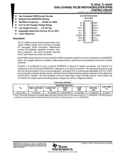
The TL1454A and TL1454AY are dual‑channel pulse‑width‑modulation (PWM) control circuits intended for low‑power DC‑DC converters such as LCD backlight inverters and notebook power supplies. Each channel includes its own error amplifier, PWM comparator, dead‑time control comparator, and MOSFET driver, while sharing a common voltage reference, oscillator, UVLO and short‑circuit protection.
Key specifications include a 3.6 V to 20 V supply range, 50 kHz‑2 MHz oscillator frequency, 1.26 V reference voltage, and up to 40 mA source/sink current per output. The device provides adjustable dead‑time (0 %‑100 % duty), UVLO protection at ~2.9 V, and short‑circuit protection that limits output current to 1 A peak.
| Oscillator frequency range | 50 kHz to 2 MHz |
|---|---|
| Supply voltage range | 3.6 V to 20 V |
| Reference voltage | 1.26 V |
| Maximum source/sink current rating | 40 mA |
| Output voltage rating | 20 V |
The oscillator can be set between 50 kHz and 2 MHz.
It operates from 3.6 V up to 20 V supply voltage.
The internal reference provides 1.26 V.