
This application note introduces the DD-128128FC-5B OLED display module and the accompanying EVK board. This application note includes module connection, power supply, timing characteristics and usage methods.
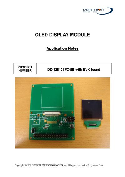
These application notes provide detailed information for the Densitron DD-128128FC-5B OLED display module and its evaluation board. The document includes EVK and DC‑DC schematics, timing characteristics, connection diagrams, power‑up/down sequences, and recommended initial code for using the module.
The note defines all relevant pins, such as the MCU interface selection pins (BS0‑BS3), reset (RES#), chip select (CS#), and power pins (VCC, VDD, VDDIO, VSL, VCOMH). Example C functions for writing commands and data over an 80‑series CPU interface are also provided.
| I/O buffer supply voltage (VDDIO) | 1.8 V |
|---|
Pins BS0, BS1, BS2 and BS3 are used to configure the MCU interface selection; BS2 and BS3 are controlled by software command 0x36.
Pull the RES# pin low to reset and initialize the chip.
Use the provided write_d function, which sets the control pins and outputs the data byte to the display.