
82C284 is a clock generator/driver from Intersil that provides clock signals for 80C286 processors and support components. It also contains logic to supply READY to the CPU from either asynchronous or synchronous sources and synchronous RESET from an asynchronous input with hysteresis.
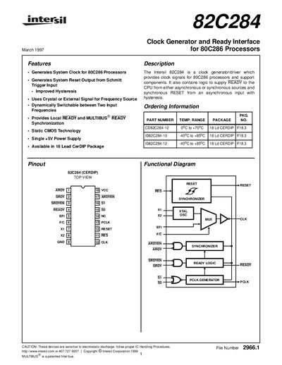
The Intersil 82C284 is an 18‑lead CERDIP clock generator/driver that provides system clock, ready and reset signals for 80C286 processors and related components. It can use an internal crystal oscillator or an external frequency source, with the F/C pin dynamically switchable between the two.
The document includes pin descriptions, functional operation of the clock, ready and reset logic, electrical characteristics, recommended crystal loading, termination guidelines, and waveform timing diagrams for both static and dynamic operation.
| Package | 18‑lead CERDIP |
|---|---|
| Input HIGH Voltage (EFI, F/C) | 3.2 V |
| READY Output Low Voltage | 0.4 V (max 10 mA) |
The F/C pin selects the clock source: low selects the internal crystal oscillator, high selects the external EFI input, and it can be switched dynamically while the system runs.
Use 25 pF from pin X1 to ground and 15 pF from pin X2 to ground (values include an additional 5 pF for stray capacitance).
READY is an open‑drain output that signals the processor that the current bus cycle is complete; it requires an external pull‑up resistor.