
X4163, X4165 16K, 2K x 8 Bit CPU Supervisor with 16K EEPROM is a low-power CPU monitor produced by Intersil. It has optional watchdog timer, low voltage detection and reset assertion.
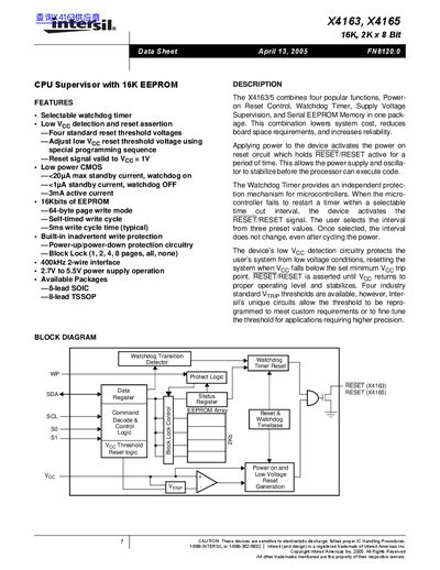
The X4163 and X4165 devices combine a power‑on reset circuit, selectable watchdog timer, low‑voltage detection and a 16‑Kbit (2K × 8) serial EEPROM in a single package. They provide system protection by holding the RESET/RESET pin active during power‑up, low‑voltage conditions, or watchdog timeout, and include non‑volatile control bits for configuring thresholds and protection features.
The devices are offered in 8‑lead SOIC and 8‑lead TSSOP packages, operate from 2.7 V to 5.5 V (or 4.5 V‑5.5 V for specific versions), and support a 400 kHz 2‑wire serial interface for EEPROM access. Detailed pin configurations, control‑register programming procedures, and timing diagrams are provided for system integration.
| EEPROM size | 16 Kbit (2 K × 8) |
|---|---|
| Standby current (watchdog on) | <20 µA |
| Standby current (watchdog off) | <1 mA |
| Reset signal valid to Vcc | 1 V |
| Package types | 8‑Lead SOIC, 8‑Lead TSSOP |
| Package types | 8‑Lead TSSOP |
| Temperature range (-40 °C – 85 °C) | -40 °C – 85 °C |
| Watchdog timer period control bits | WD1 and WD0 |
| Serial interface speed | 400 kHz 2‑wire |
RESET/RESET is an active low/high open‑drain output that goes active on power‑on reset, low‑voltage detection, or watchdog timeout and stays active until the voltage recovers.
The period is set by programming the two non‑volatile bits WD1 and WD0 in the control register.
By setting the WEL bit, applying the desired voltage to the Voc pin and a programming voltage to the WP pin, then writing the new value to the control register.
Both devices are offered in 8‑lead SOIC and 8‑lead TSSOP packages.