
The HIP4020 is a half amp full bridge power driver for small 3V, 5V, and 12V DC motors. It utilizes an H-Configuration to cross-switch the drive voltage and change the direction of current flow in the load, enabling 4-quadrant load control.
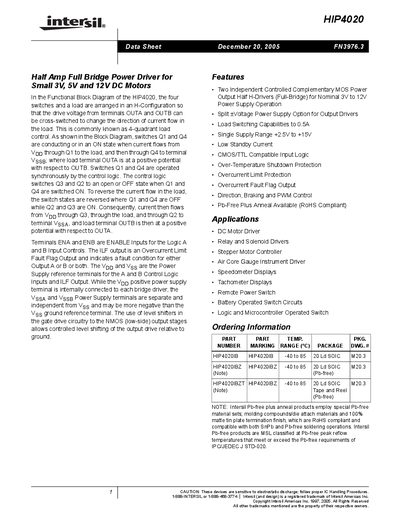
The HIP4020 is a half‑amp full‑bridge power driver designed for small DC motors operating from 3 V to 12 V. It uses an H‑configuration of four MOSFET switches to achieve four‑quadrant load control, allowing direction reversal, braking, and PWM control.
Key features include independent complementary MOS outputs, split‑supply operation, CMOS/TTL compatible inputs, over‑temperature shutdown, over‑current limit protection, and a fault flag output. Typical performance curves, pin descriptions, and package dimensions are provided for design integration.
| Input Leakage Current | 25 nA |
|---|---|
| Low Level Input Voltage (VIL) | 0.8 V |
| High Level Input Voltage (VIH) | Vbpp (typical) |
| ILF Output Low Sink Current | 15 mA |
| Input Capacitance | 2 pF |
| P‑Channel rds(on) (low supply) | 1.6‑2.1 Ω |
| N‑Channel rds(on) (low supply) | 1‑1.5 Ω |
| Idle Supply Current (no load, Vpp=5 V) | 0.8‑1.5 mA |
| Typical Output Source Current Limiting | 1500 mA (Vpp=+8 V) |
The HIP4020 operates from a typical supply voltage of +3 V to +12 V.
It includes over‑temperature shutdown protection that limits the junction temperature to about 150 °C.
ENA and ENB are enable inputs; when driven low they place the corresponding output in a high‑impedance off state.