
AD9515 is a 1.6GHz clock distribution IC with divider, delay adjustment, and two outputs.
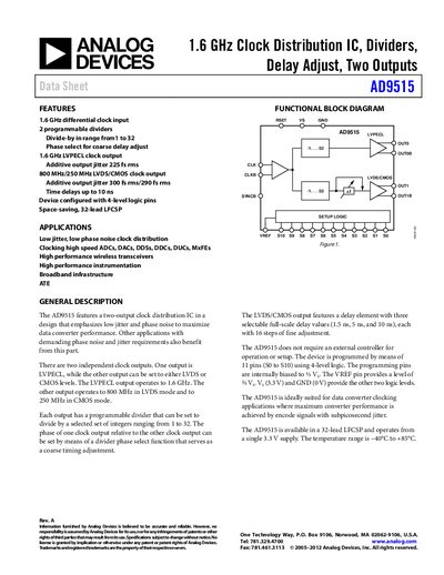
The AD9515 is a dual‑output clock distribution integrated circuit designed for low jitter and low phase‑noise performance. It offers a 1.6 GHz differential LVPECL input, two programmable dividers (1‑32), and selectable LVPECL, LVDS or CMOS output levels with fine‑adjustable delay.
Typical applications include high‑speed data‑converter clocking, wireless transceivers, instrumentation, and broadband infrastructure. The device is supplied in a 32‑lead lead‑frame chip‑scale package and operates from a single 3.3 V supply over –40 °C to +85 °C.
| Clock Input Frequency Range | 0 – 1.6 GHz |
|---|---|
| Supply Voltage | 3.3 V |
| Operating Temperature Range | –40 °C to +85 °C |
The AD9515 accepts a differential clock input up to 1.6 GHz.
One output is LVPECL, and the second can be configured as LVDS or CMOS.