
The AD9514 is a 1.6GHz clock distribution IC that includes 3 programmable dividers, delay adjustment, and three outputs.
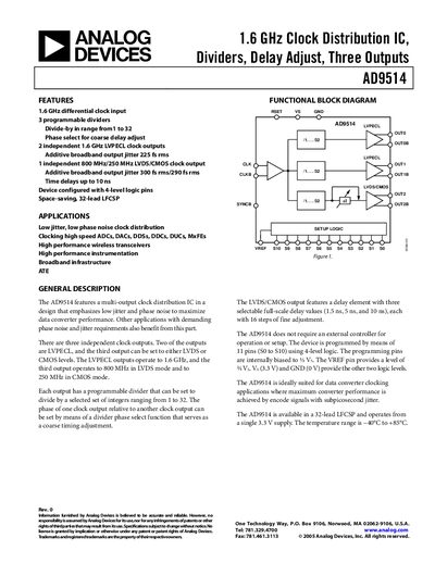
The AD9514 clock distribution IC from Analog Devices provides three independent outputs—two LVPECL up to 1.6 GHz and one selectable LVDS (800 MHz) or CMOS (250 MHz). It features programmable dividers (1‑32), coarse phase‑select delay, and fine‑step delay adjustment for precise timing.
The device is programmed via 11 pins (SO to S10) with 4‑level logic, requires no external controller, and operates from a single 3.3 V supply over a temperature range of –40 °C to +85 °C. Detailed specifications, timing characteristics, and measurement setups are provided for designers.
| Clock Input Frequency Range | 0 – 16 GHz |
|---|---|
| Clock Input Sensitivity | 150 mV p‑p |
| LVPECL Output Frequency | 1.6 GHz |
| LVDS Output Frequency | 800 MHz |
| Additive Phase Noise @10 Hz | -125 dBc/Hz |
| Operating Temperature Range | -40 °C to +85 °C |
The device operates from –40 °C to +85 °C.
The device is programmed via 11 pins (SO to S10) using 4‑level logic and does not require an external controller.
The AD9514 accepts clock inputs up to 16 GHz.