
8-Channel/4-Channel Fault-Protected Analog Multiplexers ADG508F/ADG509F Rev. F is a product manual released by Analog Devices, which introduces the features, characteristics, uses, application scenarios and other information of the product.
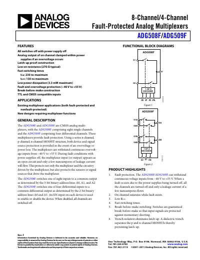
The ADG508F and ADG509F are CMOS analog multiplexers offering fault‑protected switching. The ADG508F provides eight single‑ended channels, while the ADG509F provides four differential channels. Both devices use a series n‑channel, p‑channel, n‑channel MOSFET structure to protect the device and signal source during over‑voltage or power‑off conditions.
Key features include low on‑resistance, fast switching, break‑before‑make operation, and latch‑up‑proof trench isolation. The parts are TTL and CMOS compatible and support a wide supply range of ±15 V with over‑voltage protection from –40 V to +55 V.
| Fault and overvoltage protection range | -40 V to +55 V |
|---|---|
| Typical on‑resistance (RON) | 270 Ω |
| Source off‑leakage current (I_S Off) | ±0.02 nA typ |
| Drain off‑leakage current (I_D Off) | ±0.04 nA typ |
| EN enable input behavior | All channels off when EN is low |
| Typical EN turn‑on delay (tON) | 180 ns typ |
The devices can withstand continuous voltage inputs from –40 V to +55 V.
All channels are switched off, disabling the multiplexer.
The typical on‑resistance is 270 Ω.
The typical EN turn‑on delay is 180 ns.