
ADP1612/ADP1613 are 650 kHz /1.3 MHz Step-Up PWM DC-to-DC Switching Converters with features such as current limit, adjustable output voltage, adjustable soft start, etc. They are suitable for TFT LCD bias supplies, portable applications, and industrial/instrumentation equipment.
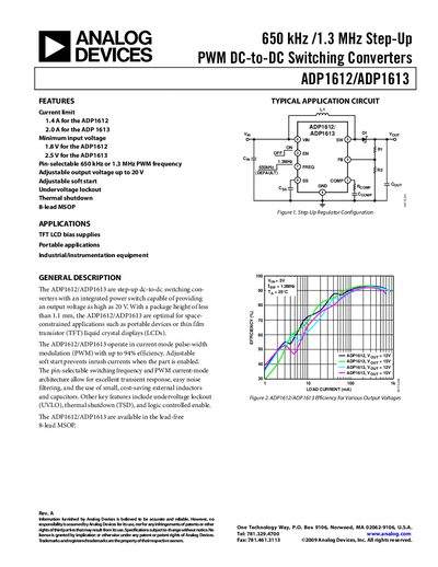
This handbook describes the ADP1612 and ADP1613 step‑up DC‑DC switching converters, highlighting features such as current limit, selectable switching frequency, adjustable output voltage up to 20 V, and built‑in protection functions. It includes typical application circuits, pin‑out details, and performance graphs.
The document contains full electrical specifications, absolute maximum ratings, thermal characteristics, and design recommendations such as inductor and capacitor selection, PCB layout guidelines, and ordering information.
| Input Voltage (Vin) – ADP1612 | 1.8 V to 5.5 V |
|---|---|
| Maximum Output Voltage | 20 V |
| Switching Frequency | 650 kHz or 1.3 MHz (pin selectable) |
| Peak Current Limit – ADP1612 | 0.9 A (min) – 1.4 A (typ) – 1.9 A (max) |
| Peak Current Limit – ADP1613 | 1.3 A (min) – 2.0 A (typ) – 2.5 A (max) |
| Thermal Shutdown Threshold | 150 °C |
| Undervoltage Lockout Threshold – ADP1612 (rising) | 1.70 V |
| Enable Pin Bias Current | 3.3 µA (min) – 7 µA (max) |
The device can be set to either 650 kHz or 1.3 MHz using the FREQ pin.
Both converters can generate an adjustable output voltage up to 20 V.