
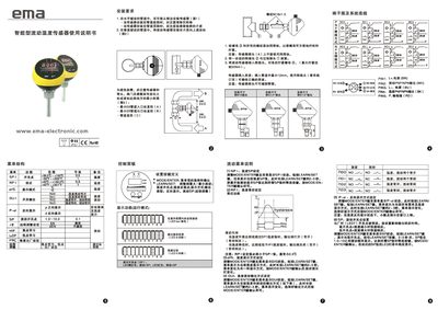
The manual describes the installation requirements for the FL0004/0005 flow sensor, recommending horizontal pipe mounting, placement on the side of the pipe, and positioning the sensor where the medium flows upward. The sensor must be inserted at least 12 mm into the pipe, use the appropriate adapter, and be tightened to a maximum torque of 50 Nm. Minimum pipe diameters are specified as 5 × A at the inlet and 3 × B at the outlet.
The control panel includes MODE/ENTER and LEARN/SET keys for menu navigation, allowing users to set flow switch points (SP), high‑point (HI‑Teach) and low‑point (LO‑Teach) adjustments, and remote adjustment via the RED pin. LED indicators show current settings, and the device offers auto‑lock functionality after two minutes of inactivity. Technical parameters such as working voltage (20‑36 VDC), IP67 protection, temperature range (‑20 °C to +80 °C), and pressure rating (300 bar) are listed in the specifications section. This manual is written in Chinese.
| Working Voltage | 20‑36 VDC |
|---|---|
| Output Response Time | <2 s |
| Current Load | 2 × 400 mA |
| Protection Rating | IP67 |
| Impact Resistance | 50 g |
| Sensor Probe Material | Stainless steel (S316L) |
| Pressure Rating | 300 bar |
| Setting Range | 3 – 300 cm |
| Maximum Sensitivity | 3 – 60 mm/s |
Mount the sensor in a horizontal pipe, preferably near the side, with the sensor placed where the medium flows upward. Insert the sensor at least 12 mm into the pipe and use the appropriate adapter to ensure correct depth.
The sensor should be tightened to a maximum torque of 50 Nm.
Press MODE/ENTER to open the menu, then use LEARN/SET to change the SP value. The current SP value is shown on the LED bar and can be set between 1.0 and 10.0.
Connect the remote adjustment wire (RED) to the power L+ terminal, press and hold LEARN/SET for 2‑3 seconds, then release to store the maximum flow rate; the LED bar lights green from left to right during the process.