
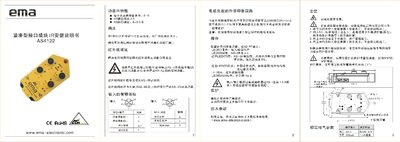
This manual describes the features and specifications of the EMA AS4122 compact interface module, including its AS‑interface version 3.0, maximum of 31 slave modules per master, and supported voltage range of DC20‑30 V. It also explains the LED status indicators for power, communication, and error conditions.
Installation steps cover disconnecting power, mounting the module on a flat surface, connecting the power and sensor cables, and configuring the address via the handheld or infrared addresser. The document includes wiring diagrams, operation guidance, and a brief maintenance note stating that no routine maintenance is required. This manual is written in Chinese.
| AS interface version | 3.0 |
|---|---|
| AS interface description | S-3.0.E |
| Maximum slave modules per master | 31 |
| Operating voltage | DC20‑30 V |
| Current limit | 100 mA |
Up to 31 slave modules can be connected to a single master module.
A continuously lit red LED 3 indicates a communication error, preventing the slave from participating in data exchange.
No maintenance is required during operation; the module only needs replacement of both halves together if serviced.