
This document describes the features and characteristics of Vishay BCcomponents Power Metal Film Resistors, including high power in small packages, different lead materials for different applications, defined interruption behavior, lead-free solder contacts, pure tin plating, compatibility with RoHS directive, etc. The product consists of a homogeneous film of metal alloy deposited on a high grade ceramic body, with a helical groove in the resistive layer and tinned connecting wires of electrolytic copper or copper-clad iron. The resistors are coated with a red, nonflammable lacquer for electrical, mechanical, and climatic protection. The product is suitable for all general purpose power applications.
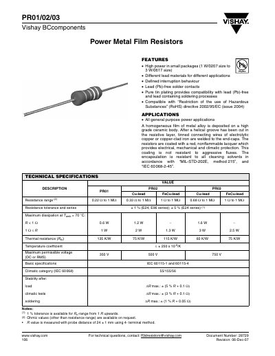
This document provides a comprehensive overview of the Vishay PR01/02/03 series of power metal film resistors. It describes the construction, lead materials, coating, and typical applications for general‑purpose power use.
The datasheet includes detailed technical specifications, dimensional drawings for straight‑lead and double‑kink styles, marking conventions, mounting guidelines, pulse‑loading capabilities, temperature‑rise data, impedance characteristics, and the full set of IEC test procedures required for qualification.
| Resistance range | 0.22 Ω to 1 MΩ |
|---|---|
| Tolerance | ±1 % (E24, E96 series) or ±5 % (E24 series) |
| Maximum dissipation (Tamb = 70 °C) – PR01 (R < 1 Ω) | 0.6 W |
| Thermal resistance (Rth) | PR01 = 135 K/W, PR02 = 75 K/W, PR03 = 115 K/W |
| Temperature coefficient | ≤ ±250 × 10⁻⁶ /K |
| Maximum voltage (DC or RMS) | PR01 = 350 V, PR02 = 500 V, PR03 = 750 V |
| Lead material options | Cu‑lead or FeCu‑lead |
The PR03 series is rated for a maximum voltage of 750 V (DC or RMS).
A PR02 straight‑lead resistor has Ø D = 3.9 mm, L1 = 10.0 mm, and L2 = 12.0 mm.
The temperature coefficient is specified as ≤ ±250 ppm/°C.
A 1 Ω PR01 resistor can dissipate up to 0.6 W at an ambient temperature of 70 °C.