
The MAX125/MAX126 are high-speed, multichannel, 14-bit data-acquisition systems (DAS) with simultaneous track/holds (T/Hs). These devices contain a 14-bit, 3µs, successive-approximation analog-to-digital converter (ADC), a +2.5V reference, a buffered reference input, and a bank of four simultaneous-sampling T/H amplifiers that preserve the relative phase information of the sampled inputs. The MAX125/MAX126 have two multiplexed inputs for each T/H, allowing a total of eight inputs. In addition, the converter is overvoltage tolerant to ±17V; a fault condition on any channel will not harm the IC. Available input ranges are ±5V (MAX125) and ±2.5V (MAX126). An on-board sequencer converts one to four channels per CONVST pulse. In the default mode, one T/H output (CH1A) is converted. An interrupt signal (INT) is provided after the last conversion is complete. Convert two, three, or four channels by reprogramming the MAX125/MAX126 through the bidirectional parallel interface. Once programmed, the MAX125/MAX126 continue to convert the specified number of channels per CONVST pulse until they are reprogrammed. The channels are converted sequentially, beginning with CH1. The INT signal always follows the end of the last conversion in a conversion sequence. The ADC converts each assigned channel in 3µs and stores the result in an internal 14x4 RAM. Upon completion of the conversions, data can be accessed by applying successive pulses to the RD pin.
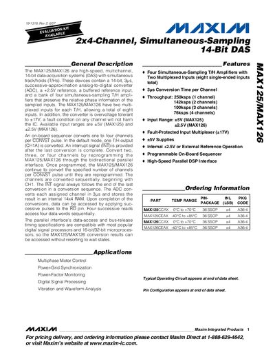
The MAX125 and MAX126 are high‑speed, 14‑bit data‑acquisition converters featuring four simultaneous‑sampling track‑and‑hold amplifiers. Each T/H has two multiplexed inputs, providing up to eight single‑ended inputs. The devices support programmable on‑board sequencing, a high‑speed parallel DSP interface, and over‑voltage tolerant inputs up to +17 V.
Key specifications include a typical throughput of 250 ksps per channel, input voltage ranges of +5 V for MAX125 and +2.5 V for MAX126, and a power dissipation of up to 250 mW. The datasheet also provides absolute‑maximum ratings, electrical characteristics, timing diagrams, pin descriptions, and package dimensions.
| Resolution | 14 Bits |
|---|---|
| Throughput (1 channel) | 250 ksps |
| Input Voltage Range (MAX125) | +5 V |
| Power Dissipation | 250 mW |
The MAX125 accepts an input voltage range of up to +5 V.
The devices can achieve up to 250 ksps per channel.
Each device includes four simultaneous‑sampling track‑and‑hold amplifiers.
The acquisition time is typically 1 µs.