
LCP02-150B1 is an integrated circuit for protecting ringing SLICs, widely used in SLICs with dual battery supplies, negative battery supply configuration, and negative and positive battery supply configuration.
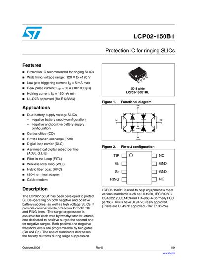
The LCP02-150B1 is a protection IC designed for ringing SLICs that operate on both negative and positive battery supplies. It provides crowbar‑mode protection for TIP and RING lines, with programmable positive and negative firing thresholds and low gate‑triggering current.
The document lists electrical characteristics, thermal data, package dimensions, ordering codes, and compliance with standards such as UL497B, UL1950, IEC 60950 and TIA‑968‑A. It also includes application notes for central office, PBX, ADSL, FITL, WLL and other telecom environments.
| Peak pulse current | 30 A (10/1000 ps) |
|---|---|
| Holding current (minimum) | 150 mA |
| Gate decoupling capacitance | 100 nF – 220 nF |
| Maximum negative battery voltage | -120 V to 0 V |
| Maximum positive battery voltage | 0 V to +120 V |
| Operating temperature range | -40 °C to +125 °C |
| Junction‑to‑ambient thermal resistance | 150 °C·W |
The device can handle a peak pulse current of 30 A measured over 10/1000 ps.
A gate decoupling capacitance between 100 nF and 220 nF is recommended.
It is UL497B approved and complies with standards such as UL1950, IEC 60950, and TIA‑968‑A.
The IC can operate with a negative battery voltage from –120 V up to 0 V.