
This document introduces the features and characteristics of the HMW50U/Y product, including electrical connections and installation instructions
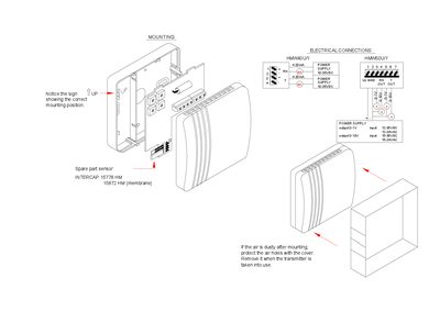
The guide shows the correct mounting position for the HMW40/50 sensor, indicating the sign that points upward. It also advises protecting the air holes with a cover when the environment is dusty and removing the cover once the transmitter is in use.
Electrical connection details are provided, including power supply options (10‑35 VDC, 12‑24 VAC, 15‑35 VDC, 15‑24 VAC) and output signal ranges (0‑1 V, 0‑10 V, 4‑20 mA). Spare part sensor numbers (INTERCAP 15778 HM, 15872 HM) are listed for reference.
| Power supply voltage (DC) | 10‑35 VDC |
|---|---|
| Power supply voltage (AC) | 12‑24 VAC |
| Power supply voltage (DC) alternative | 12‑35 VDC |
| Power supply voltage (DC) alternative 2 | 15‑35 VDC |
| Power supply voltage (AC) alternative | 15‑24 VAC |
| Output signal range (voltage) | 0‑1 V |
| Output signal range (voltage) | 0‑10 V |
| Output signal range (current) | 4‑20 mA |
The guide shows a sign pointing upward that indicates the correct mounting position.
Cover the air holes with the provided cover and remove it when the transmitter is taken into use.