
TLP115A is a photocoupler produced by TOSHIBA. It has high output power, high switching speed, high isolation distance and other characteristics. It is suitable for digital isolation, A/D, D/A conversion and other occasions.
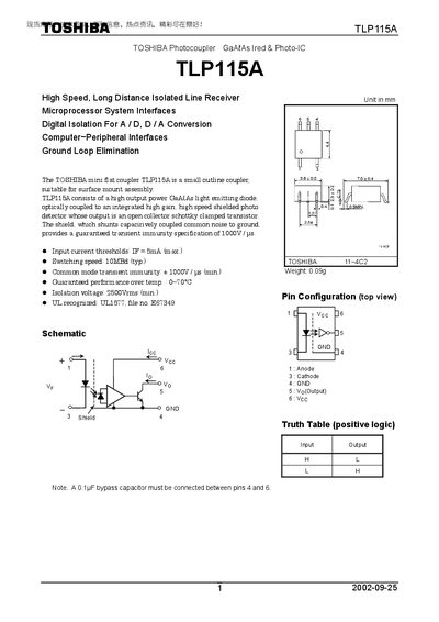
The TLP115A is a miniature GaAs optocoupler with a high‑output power LED optically coupled to a high‑gain, high‑speed shielded photodetector. It is supplied in a small outline surface‑mount package and is intended for digital isolation in microprocessor interfaces, A/D and D/A conversion, and ground‑loop elimination.
The datasheet lists maximum ratings, electrical characteristics, switching performance, and recommended test circuits. It also includes handling precautions, isolation voltage requirements, and usage restrictions for safety‑critical applications.
| Isolation voltage (AC, 1 min, 60% RH) | 2500 Vrms (min) |
|---|---|
| Input current threshold (IF) | 5 mA (max) |
| Switching speed | 10 MBd (typ) |
| Low‑level output current (sink) | 13 mA |
| Supply voltage (Vcc) | 4.5 V – 5.5 V |
| Operating temperature range | -40 °C to 85 °C |
The device is rated for a minimum isolation voltage of 2500 Vrms (AC, 1 min, 60 % RH).
The recommended supply voltage (Vcc) is between 4.5 V and 5.5 V.
The device can operate from –40 °C up to 85 °C.
A 0.1 µF capacitor (ceramic or solid tantalum) should be placed as close as possible to the Vcc and GND pins.