
TL494 is a pulse-width-modulation (PWM) control circuit that incorporates complete power control circuitry and offers flexibility to tailor the power-supply control circuitry to a specific application. It contains two error amplifiers, an on-chip adjustable oscillator, a dead-time control comparator, a pulse-steering control flip-flop, a 5V, 5%-precision regulator, and output-control circuits.
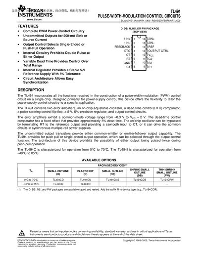
The TL494 is a pulse‑width‑modulation (PWM) control integrated circuit designed primarily for power‑supply applications. It integrates two error amplifiers, an adjustable on‑chip oscillator, dead‑time control, a precision 5 V regulator, and output‑control circuits, offering both single‑ended and push‑pull operation.
The document provides absolute maximum ratings, recommended operating conditions, electrical characteristics, mechanical data, and a detailed notice on product warranties and usage. It also lists the available package types and temperature ranges for the TL494C and TL494I variants.
| Recommended supply voltage (Veco) | 7 V to 40 V |
|---|---|
| Maximum collector output current (each transistor) | 200 mA |
| Oscillator frequency range | 1 kHz to 300 kHz |
| Timing capacitor range | 0.47 nF to 10 µF |
| Available package types | D, DB, NS, PW (tape‑and‑rewind) |
| Operating temperature range | 0 °C to 70 °C (TL494C) / –40 °C to 85 °C (TL494I) |
The TL494 operates with a recommended supply voltage between 7 V and 40 V.
The TL494 is available in D, DB, NS, and PW surface‑mount packages, which can be supplied taped and reeled.
The on‑chip oscillator can be set to operate from 1 kHz up to 300 kHz.
Each output transistor can source or sink up to 200 mA under recommended conditions.